How a CNC controller works


A controller or control unit is the heart of every CNC machine, whether it is a milling machine, a lathe, a plasma cutter or similar. It's also the part which is changing the most: while the mechanical construction of most machines has been pretty similar over the last few decades, the software part is updated frequently, with new features being added, changing designs and improved performance.
It's also the part that is most mysterious to the end user. While you can see how the machine moves and how it is constructed, the controller mostly is a black box.
This article aims to help you get a better understanding of the brain of a CNC controlled machine.
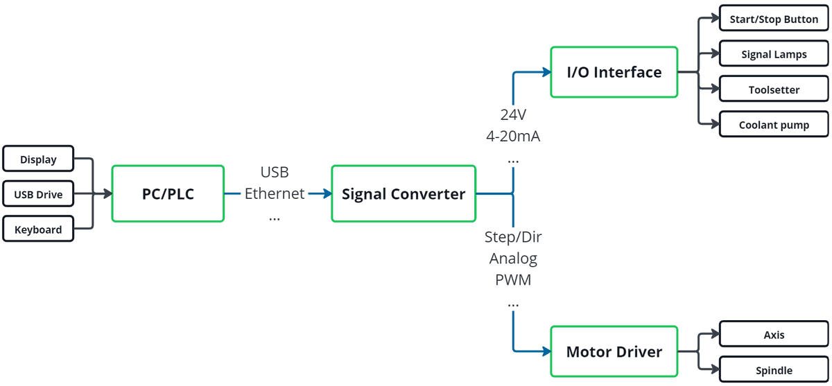
Components of a CNC machine controller
There are many different types of controllers on the market today and while they all have their differences, the basic principle is mostly the same. The majority consists out of 3 parts.
The brain
The brain or the unit responsible for computing is the main part of the control. There are 2 different approaches for this part: PC and PLC based control.
The PC based approach uses a computer like yours at home. While the operating system might be a bit more tailored for industrial control, the principle is the same. You boot up the PC and then run an application which is responsible for controlling your machine and interacting with the user interface. In industrial controllers, this often happens automatically and you don't have access to the other functions of the computer, but this is just for convenience and safety reasons.
PLC based control is very similar, but instead of a PC a PLC is used. PLC stands for "programmable logic controller" and is used heavily in industry applications. You can think of it as a normal PC, but with limited functionality and specifically tailored for industrial use. For example only specific programming languages can be used, it's more reliable (doesn't crash randomly like your Windows sometimes does) and better protected against water and dust. You can often combine them directly with digital, analog or other IO interfaces for machine control.
The software running on the chosen hardware is responsible for the control. Different software offers different functionality for different machines, but the basic ones for lathes and mills are:
- Digital position displays
- Manual axis movement
- Referencing the machines endpoints
- Running gcode programs
Motor drivers
The motors for the axis and the spindle are "dumb". They mostly consist out of coils and magnets so in order to control them you need to deliver the right current, voltage and frequency to them. This is what a motor driver does. It converts "data" coming from the PC into actual electricity used to run the motors.
There are many types of motors and each one needs a specific suited driver. For example, servo motors work differently than stepper motors, so you need a servo driver, a stepper motor driver won't work. The power of the motor is also important. There are drivers for huge motors and there are drivers for very tiny motors, and everything in between. Generally speaking, the more power a motor uses, the bigger and more expensive are the drivers.
The input signals a driver needs can also vary. Most common are step/direction, analog +/-10V or PWM signals. The advantage of separating the motor driver from the brain is that you can use the same software and pc/plc to control all kinds of motors. You just need the fitting driver.
Another advantage is that this separates the "high current" part from the "data/calculation" part of the system, which is generally good practice in engineering.
Signal Converters
As described above, motor drivers need specific signals in order to run correctly. The problem is, that normal PCs don't have an output for those signals. They mostly only have ethernet, USB and sometimes parallel ports, but none for example for +/-10V.
This is where a signal converter comes into play. The software on the PC generates commands and sends them over USB or ethernet to the signal converter. The signal converter then converts the USB/ethernet data to signals a motor drive can work with.

Sometimes these modules also do a bit of data postprocessing. The faster/more accurate the movement of the motor needs to be, the faster the commands have to be. If the PC is not fast enough (sometimes these signals need to be below a microsecond), a FPGA on these modules can take over the high speed part.
These converters not only implement the direct motor control, but also often come with options for digital and analog IO pins, encoder inputs and many more.
In industrial and PLC based controls, the signal converter is often already built into the controller. You then buy a complete package containing the software, PLC and converter ready to go.
For cheaper controls there is often a lot more tinkering needed. You need to select a fitting PC, can choose between thousands of different control applications and signal converters. On the other hand, this also leads to more freedom and customisability.
Popular choices for industrial controllers are HEIDENHAIN, Siemens and Fanuc.
For hobby use there are a lot more choices but some of the most popular include LinuxCNC, EdingCNC and Estlcam.
Complete workflow
To better understand the whole design, here is an example of running a job with a CNC mill and the responsible controller parts.
Generating a program
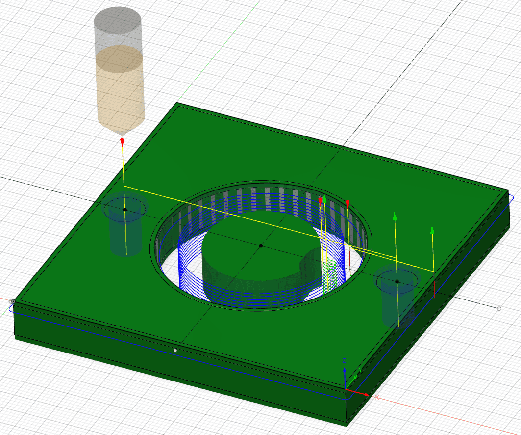
To tell the machine what it is supposed to do, we need to write a program. The format of this program is mostly gcode. You can either write the whole program by hand or let a CAM program do the work for you. A CAM program takes a CAD model of the part you want to manufacture and generates the gcode with the necessary movements.
Manual programming was used in the early days of CNC machining and might be faster for smaller projects with just a few lines. To aid you with that, there are often "macros" for special operations like pockets available, which speed up the programming task.
Complex parts, especially with more than 3 axis used can contain thousands of gcode lines. This is not possible with manual programming but needs a CAM to generate the toolpath. The CAM program also helps you with different machining strategies, tool libraries and part fixturing.
Running the program
After loading the gcode into the machine controller, you can run it. The gcode file is analyzed by your controller application and turned into machine readable motion commands, meaning the exact moves the individual axis have to make in order to mill correctly. When running the program, the file is executed line by line. The backend of the software sends the commands to the signal converter or directly to the motor drives. The drives then adjust the motors voltage, current and frequency to move exactly the way commanded. Encoders on the axis or the motors determine the actual position of the axis and report it back to the application. This is called a "closed loop" system. With this feedback and the next moves in mind, the software calculates the new moves the axis have to make. You can think of it as the navigation system in your car, but in much smaller scale and way faster. The software can also control coolant pumps, vacuum plates, touch probes and much more.